
Basic information about cutting tools
Diamond, PCD & PcBN
Diamond, PCD & PcBN
Diamond
(MCD: Mono-crystal diamond, Single-crystal diamond)
Diamond is a mineral composed of carbon, and is the hardest natural substance. It is written in kanji as "金剛石" (Kongoseki). The unit of quantity is carat (ct), which is the weight unit of gemstones. One carat is 0.2 grams.
There are two types of mono-crystal diamonds: natural and synthetic. Natural diamonds are subjected to a variety of environments, from high temperatures and pressures deep beneath the earth’s surface until they are pushed up with the magma to near the surface over hundreds of millions of years, resulting in some individual differences. Synthetic diamonds can be produced stably with the desired quality because the environment and growth conditions for synthesis can be controlled. Although synthetic diamonds are widely used in industrial applications, natural diamonds have better wear resistance. We offer tools that use synthetic and natural diamonds making use of the each characteristic.
PCD
(Polycrystalline sintered diamond)
This diamond is made by sintering microcrystals of synthetic diamond with a binder (metal or ceramics) at high temperature and high pressure. Since the sintered diamond particles are oriented in a variety of directions, this type of diamond does not have the cleavage property (the tendency to break in a specific direction) of a mono-crystal diamond, and is difficult to break or peel from any direction of force.
PcBN
(Polycrystalline cubic Boron Nitride)
In the machining of metal materials, especially iron-based materials, the carbon of diamond diffuses and permeates the iron structure in the material, and diamond, which is supposed to be hard, wears out unexpectedly quickly. Therefore, diamond tools are not suitable for machining iron-based materials.
The next hardest material after diamond is cBN (an acronym for cubic Boron Nitride, written as "CBN" in product names), a compound that does not exist naturally.
PcBN, which is used for cutting tools, is made under an environment of ultra-high pressure and temperature by mixing cBN crystal grains with binders such as ceramics and metals.
It is inferior to diamond in terms of hardness at room temperature, but since it does not contain carbon, it is suitable for processing iron-based materials. By using diamond and PcBN differently depending on the material to be processed, it is possible to achieve machining that makes the most of their respective features.
Cutting process and cutting tools
Cutting process
Cutting is one of the removal processes in which the cutting edge is used to remove chips where the tool passes. There are three types of cutting processes: turning, in which the tool is applied to a rotating work material, milling (cutting by rolling), in which the rotating tool is applied to a stationary work material, and drilling.
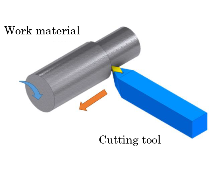
Lathe machining
Turning machines, which excel in machining round objects, are often used for lathe machining. Lathe machining is a process in which a cylindrical or disk-shaped round work material is rotated and cut by applying the tool while moving it in a certain direction.
Lathe machining is used for outer diameter machining, inner diameter machining, taper cutting, boring, drilling, threading, and thrust cutting. With a 4-jaw chuck, squares and other shapes can also be machined.
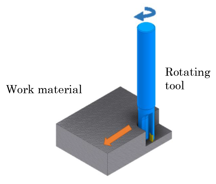
Milling
Milling machines (with rotating tools), which are good at machining square objects, are often used for milling. While rotating the tool, the work material fixed on the worktable that moves back and forth, left and right, is machined.
Using a milling machine, end mills and other tools are mounted to perform flat machining, step and side machining, pocket and groove machining, key groove machining, T-slot machining, dovetail groove machining, and curved surface machining.
Hole drilling
The work material is fixed in place and the tool is rotated to drill or adjust a hole.
Drills are used to drill holes, and reamers are used to widen the inner diameter of the hole to a predetermined dimension after drilling, and to adjust the accuracy of the interior side of the hole.
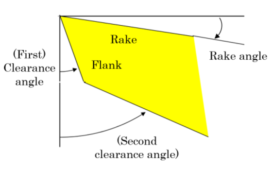
Cutting tool edge
The cutting edge of a cutting tool has a rake that is angled (at a rake angle) to feed chips from the work material and a flank that is perpendicular to the rake and angled (at a clearance angle) so that only the cutting edge contacts the work material.
The rake angle determines the cutting ability and the clearance angle determines the finish of the machined surface. A second clearance angle may be added to the flank to prevent interference with the work material.
Profile (waviness) of cutting edge
The line/surface profile is defined by JIS (Japanese Industrial Standards) as "the magnitude of deviation of the profile of a line/surface from the geometrically correct contour as determined by theoretically accurate dimensions." The profile of the cutting edge of cutting tools with a round cutting edge is a measure of whether the roundness-curve of the W.A. part is as designed. The smaller the value, the smaller the deviation from the design.
Our "Arcceed" mono-crystal diamond cutting tool has achieved a profile of less than 50 nm.
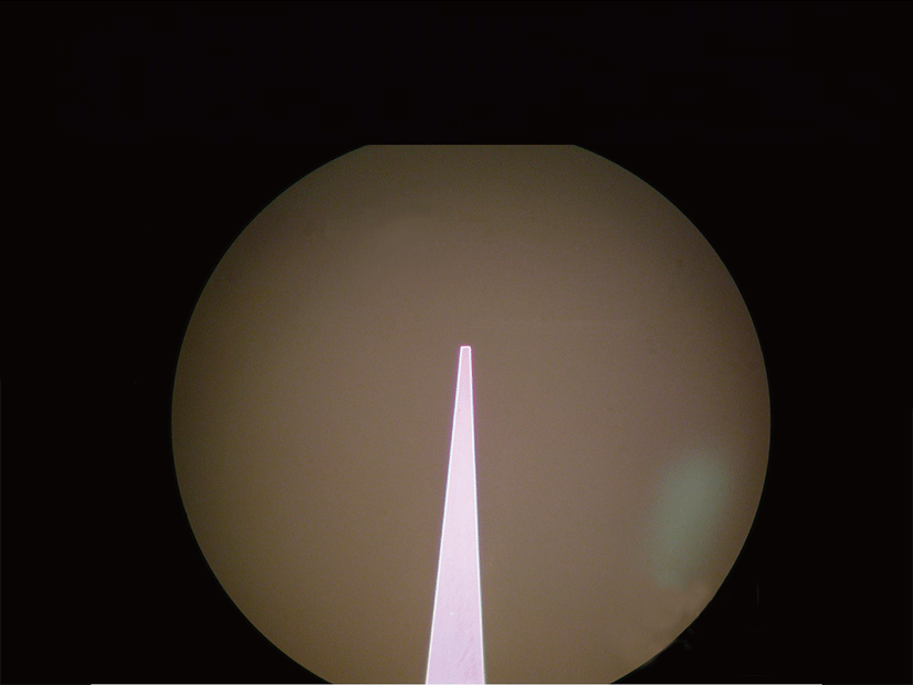
Cross-sectional image of cutting tool edge
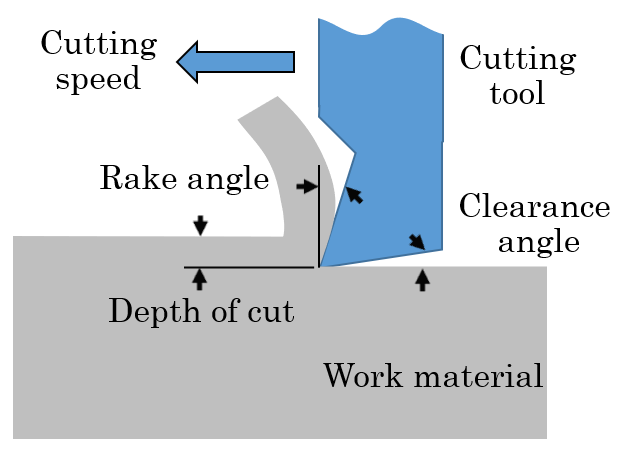
Cutting condition
The cutting speed (peripheral speed), depth of cut, and feed rate (amount of feed) are called the cutting conditions. In lathe machining, there is a relative motion between the tool and work material, and cutting conditions affect dimensional accuracy, finished surface, and tool life. Therefore, it is important to select the appropriate conditions that match the material to be machined, the tool mounting method, and the machine performance.
The cutting speed is the speed at which the cutting edge cuts the work material (the speed at which the cutting tool rotates), and the larger the diameter of the work material, the faster the cutting speed.
The depth of cut is the depth of penetration of the tool into the center of the work material. The larger the depth of cut, the higher the cutting efficiency but the greater the force required. Too small depth of cut generally results in larger back forces, which can cause chattering.
The feed rate (feed amount/table feed) is the distance that the tool travels per revolution. It is also referred to as the speed at which the tool moves. The faster the travel speed, the higher the cutting efficiency, but the rougher the machined surface.
Image of cutting process
Types of cutting tools
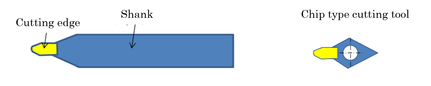
Cutting tool
A cutting tool for use with a lathe, basically consisting of a cutting edge and a shank (body part). The shank is mounted on the lathe and pressed against the rotating work material for machining.
In addition to the integrated type of cutting edge and shank, there are also types in which the chip shank (middle shaft) with cutting edge is fixed to a holder with screws, and small chip type (middle shaft type) cutting tool that is fixed with screws or other devices to prevent them from becoming large folders.
Sword cutting tool
A cutting tool consisting of two straight cutting edges.

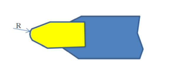
Round edge cutting tool (round-sword cutting tool)
A cutting tool with a round cutting edge.
Flat sword cutting tool (flat cutting tool)
A cutting tool with a flat and straight blade edge.

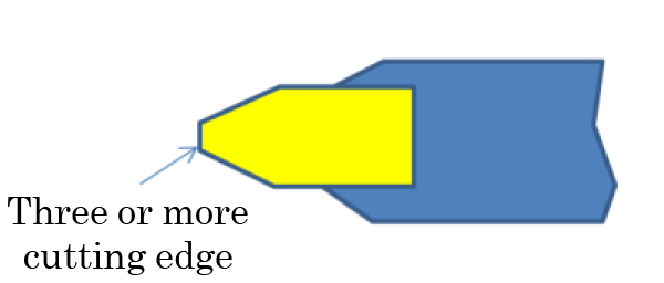
Polygonal cutting tool
Polygonal cutting tool with three or more cutting edges.
Right-hand and left-hand
Some of the tools used in general-purpose lathes (manual machining machines with X- and Z-machining axes) have their cutting edges tilted to either the right or left side relative to the shank. When the work material is in forward rotation (counterclockwise when looking at the spindle from the tail stock) and the tool is moved from right to left to cut the work material, the tool is called a "right-hand" tool, and when the tool is moved from left to right to cut the work material, the tool is called a "left-hand" tool. (Tail stock: Stand to hold the end of the work material from the opposite side of the chuck)
The one with a sword edge is called a tilted sword cutting tool, and the one with a round edge is called a round-edge tilted sword cutting tool.
Tilted sword cutting tool: Right-hand

Tilted sword cutting tool: Left-hand

End mill
A type of milling tool that is attached to a milling machine and is used to machine a work material fixed on a work table that moves back and forth, left and right, while rotating. In contrast to a drill, which propels the work material in the axial direction and drills a hole, this milling tool uses a side cutting edge for machining.
It is capable of cutting and expanding holes in the direction perpendicular to the axis, finishing to smooth end faces, and machining work materials such as molds in a variety of shapes including holes, grooves, flat surfaces, and three-dimensional curved surfaces, as well as finishing with high surface accuracy.
These include flat end mills (with a flat tip), ball end mills (with an arc-shaped tip), and radius end mills (with a round corner on the bottom edge).
Reamer
The reamer widens the inner diameter of a hole pre-drilled by a drill to a predetermined dimension, or adjusts the accuracy of the inner side of the hole.
While mounted on the spindle of a drilling machine and rotated, it is lowered toward the work material fixed on the table to machine the hole.
Other machining machines such as lathes and milling machines can also perform drilling, but the drilling machine is specialized for drilling.
Example of cutting edge shapes of MCD tools
| Cutting tool type | Cutting edge shape | Work examples |
|---|---|---|
| Straight cutting tool |
 |
Optical device molds, Fresnel lens molds, prism sheet molds and light guide plate molds |
| Ultrafine radius cutting tool |
 |
Optical device molds, contact lenses, intraocular lenses, and acceleration tube cells |
| Round-nose cutting tool |
 |
Lens molds, contact lenses, flat surface machining, and free form surface machining |
| Aspheric round-nose cutting tool |
 |
Flat display panel sheet molds, prism sheet molds |
| Inverse round-nose cutting tool |
 |
Light guide panel molds |
| Ball end mill |  |
Micro lens arrays, special polygon mirrors |
| Square nose Cutting tool |
 |
Drums for photoconductive printers, camera lens barrels, decorative metalworking |
| Ultrafine cutting tool |
 |
Optical device molds, flat panel display sheet molds, fine groove machining |
| Two-edge formed cutting Tool |
 |
Machining efficiency can be improved with two peaks on a mono-crystal diamond. |
| Parallel two-edge cutting tool |
 |
With two edges in parallel, this cutting tool can simultaneously perform rough machining and shape transfer machining. It can also handle different shapes and make height adjustments. |